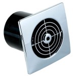
Understanding Bathroom Vent Fan with Light Wiring Diagrams
A bathroom vent fan with a light is a common and beneficial fixture in many households. It serves two critical functions: removing moisture and odors from the bathroom and providing illumination. Proper installation and maintenance of these fans require a solid understanding of their wiring. This article delves into the intricacies of bathroom vent fan wiring diagrams, providing comprehensive knowledge for a safe and effective installation.
The primary purpose of a bathroom vent fan is to mitigate moisture buildup. Excessive humidity in bathrooms can lead to mold growth, damage to paint and drywall, and general discomfort. The fan draws out humid air, preventing these issues. The integrated light provides essential illumination for tasks such as showering, grooming, and using the facilities. A properly wired fan is crucial for both its functionality and safety, reducing the risk of electrical hazards.
A wiring diagram is a visual representation of an electrical circuit. It illustrates how the different components are connected using wires. In the context of a bathroom vent fan with a light, the diagram shows the connections between the power source, the fan motor, the light fixture, and any switches or controls. These diagrams are essential for correctly connecting the wires and ensuring the device functions as intended without creating safety hazards.
Key Components in a Bathroom Vent Fan Wiring System
Understanding the components involved is crucial before diving into the specifics of wiring diagrams. The main components include the power source, the fan motor, the light fixture, the switches, and the wiring itself. Each component plays a distinct role in the operation of the system.
The power source is typically a 120V AC circuit provided by the home's electrical system. This circuit is usually protected by a circuit breaker in the main electrical panel. It is important to ensure that the circuit is properly rated for the load of the fan and light to prevent overloading and potential fires.
The fan motor is responsible for driving the fan blades, which exhaust air from the bathroom. This motor requires a specific voltage and current to operate efficiently. Exceeding or reducing these parameters can damage the motor or affect its performance. The wiring diagram will indicate which wires connect to the motor and their corresponding voltage levels.
The light fixture provides illumination for the bathroom. It may consist of a single bulb or multiple bulbs, depending on the model of the fan. Similar to the fan motor, the light fixture requires a specific voltage and current to operate correctly. The wiring diagram will show how the light fixture is connected to the power source and controlled by a switch.
Switches control the operation of the fan and light. They may be separate switches for each function, or a single switch that controls both. In some cases, a timer switch may be used to automatically turn off the fan after a set period. The wiring diagram indicates how the switches are connected to the fan motor and light fixture, allowing the user to control their operation independently or together.
The wiring consists of insulated copper conductors that carry electrical current between the different components. These wires are typically color-coded to identify their function. Black wires are generally used for the hot (live) conductor, white wires for the neutral conductor, and green or bare copper wires for the ground conductor. The wiring diagram will specify the gauge (size) of the wires required for the circuit, which depends on the current-carrying capacity needed.
Types of Bathroom Vent Fan Wiring Diagrams
Different types of wiring configurations exist for bathroom vent fans with lights. The specific wiring diagram used will depend on the features of the fan and the desired control methods. The most common types include single-switch operation, separate-switch operation, and timer-controlled operation.
In a single-switch operation, one switch controls both the fan and the light simultaneously. When the switch is turned on, both the fan and light are activated. This is the simplest wiring configuration and is commonly found in older installations. The wiring diagram for this type of setup shows the power source connected to the switch, which then feeds power to both the fan motor and the light fixture in parallel. This configuration is straightforward to implement but lacks individual control over the fan and light.
Separate-switch operation allows the fan and light to be controlled independently by two different switches. This configuration provides greater flexibility, allowing the user to operate the fan without the light or vice versa. The wiring diagram for this setup shows the power source connected to two separate switches, one for the fan and one for the light. Each switch then feeds power independently to its respective component. This configuration is more complex than the single-switch setup but offers greater user control and energy efficiency.
Timer-controlled operation incorporates a timer switch that automatically turns off the fan after a preset period. This is useful for ensuring that the fan continues to run for a sufficient time to remove moisture after a shower, even if the user forgets to turn it off. The wiring diagram for this setup shows the power source connected to the timer switch, which then feeds power to the fan motor. The light may be controlled by a separate switch, or it may be wired to turn on automatically when the fan is activated. Timer switches are available in various forms, including mechanical and electronic versions, each with slightly different wiring requirements.
Some advanced systems may include humidity sensors that automatically activate the fan when the humidity level in the bathroom exceeds a certain threshold. These systems typically require more complex wiring and may involve additional control circuitry. The wiring diagram for a humidity-sensing fan will show the sensor connected to a control module, which then controls the operation of the fan motor. The light may still be controlled by a separate switch or integrated into the humidity-sensing system.
Interpreting a Bathroom Vent Fan Wiring Diagram
Effectively reading and understanding a wiring diagram is essential for safe and correct installation. Wiring diagrams use symbols and conventions to represent the various components and their connections. Familiarity with these symbols and conventions will greatly aid in interpreting the diagram and performing the wiring accurately.
A typical wiring diagram will include symbols for the power source, switches, fan motor, light fixture, and wiring connections. The power source is often represented by a symbol resembling a battery or a sine wave, indicating AC power. Switches are typically represented by a symbol showing a break in the circuit, which can be opened or closed to control the flow of electricity. The fan motor and light fixture are usually represented by symbols specific to those components, often resembling a motor winding or a light bulb, respectively.
Wiring connections are represented by lines that connect the various symbols. These lines indicate the path of the electrical current between the components. The color of the lines may also be used to indicate the type of wire being used, such as black for hot, white for neutral, and green for ground. It is important to pay close attention to the polarity and color coding of the wires to ensure that the connections are made correctly. Incorrect wiring can result in malfunctioning equipment, electrical shock, or even fire.
The wiring diagram will also indicate the voltage and current ratings of the different components. This information is crucial for selecting the correct size of wires and circuit breakers to ensure that the circuit is properly protected. Using undersized wires can cause them to overheat and potentially start a fire. Using an over-sized circuit breaker may not provide adequate protection for the circuit.
In addition to the symbols and connections, the wiring diagram may also include notes and instructions that provide additional information about the installation process. These notes may specify the type of wire to use, the location of the components, or any special precautions that need to be taken. It is important to read and understand these notes carefully before beginning the installation.
Following the wiring diagram meticulously is paramount for a safe and functional installation. Deviating from the diagram can lead to incorrect connections, which may result in damage to the equipment or pose a safety hazard. It is always advisable to consult with a qualified electrician if there are any doubts or uncertainties about the wiring process.
Safety Precautions When Working with Electrical Wiring
Working with electrical wiring can be dangerous if proper precautions are not taken. It is essential to follow safety guidelines to prevent electrical shock, burns, or other injuries. Always prioritize safety when working with electrical systems.
The first and most important safety precaution is to disconnect the power to the circuit before beginning any work. This can be done by turning off the circuit breaker that supplies power to the bathroom vent fan. Use a voltage tester to confirm that the power is indeed off before touching any wires. Never assume that the power is off, even if the switch is in the "off" position.
Wear appropriate personal protective equipment (PPE) when working with electrical wiring. This includes safety glasses to protect the eyes from sparks or debris, and insulated gloves to protect the hands from electrical shock. Avoid wearing loose clothing or jewelry that could get caught in the wiring.
Use insulated tools designed for electrical work. These tools have non-conductive handles that provide protection from electrical shock. Avoid using tools with damaged or worn insulation. Inspect tools regularly for any signs of damage.
Work in a well-lit and dry environment. Water can conduct electricity, so it is important to avoid working with electrical wiring in damp or wet conditions. Good lighting will help to see the wiring clearly and avoid making mistakes.
Double-check all wiring connections before restoring power to the circuit. Ensure that all wires are securely connected and that there are no loose strands or exposed conductors. Use wire nuts or other approved connectors to make secure and reliable connections.
If you are not comfortable working with electrical wiring, it is best to hire a qualified electrician to perform the installation. An electrician has the knowledge and experience to safely and correctly install the bathroom vent fan. Working with electricity is not something to be taken lightly, and it is always better to err on the side of caution.

Bookingritzcarlton Info Bathroom Fan Light Exhaust

Exhaust Fan Wiring Single Switch Bathroom Light

Exhaust Fan Wiring Diagram Timer Switch

Bathroom Exhaust Fan Light

How To Make Bathroom Light In Exhaust Fan Wiring Diagram Connection

Bathroom Exhaust Fan With Humidity Sensor On One Switch Home Improvement Stack Exchange

Wiring Diagrams For A Ceiling Fan And Light Kit Bathroom Exhaust Home Electrical Switch

How To Make Bathroom Light In Exhaust Fan Wiring Diagram With

Delayed Bathroom Exhaust Fan Functional Devices Inc

Hvacquick How To S Wiring 1 Fan Serving 2 Baths With Switch Per Bath Lights From Com
Related Posts


